This is the last article in our series about what it takes to develop a complex electronic product in China. We’ll look at ways to save on the costs of electronic components, and how to make assembly easier.
Ideally, your Chinese contract manufacturer would help you on this topic. Especially with making assembly easier, since it translates into fewer quality issues and delays. In reality, it is up to the buyer & designer to come up with these types of improvements.
1. Cost Saving Attributes
There are several attributes you should consider when looking at reducing cost. In this section we’ll look at 2 attributes regarding electronics.
(Keep in mind, these cost saving activities should not compromise the overall quality or functionality of the product.)
Attribute 1: architecture
Consider basing the architecture on the latest-technology integrated chips which allow for a combination of functions to be densely packed into a single integrated chip. Here are three examples:
- Very-large-scale integration (VLSI) is the process of creating an integrated circuit (IC) by combining thousands of transistors into a single chip. An electronic circuit might consist of a CPU, ROM, RAM and other glue logic. VLSI lets IC designers add all of these into one chip.
- A field-programmable gate array (FPGA) is an IC that can be programmed in the field after manufacture.
- An application-specific integrated circuit (ASIC) is an IC customized for a particular use, rather than intended for general-purpose use.
(Chip selection factors were covered in a previous section of the series so we will not cover chip selection here.)
Attribute 2: reducing inter-board wiring complexity
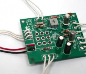
In order to reduce assembly cost and avoid quality issues, you should minimize all inter-board wiring, which is traditionally achieved through hand soldered wires.
A better way of achieving inter-board connectivity is by plugging one PCB directly into another PCB where all connectors are automatically placed and soldered. The image below shows the poor example of soldered wires for connections (time consuming in production, and in the end additional costs).
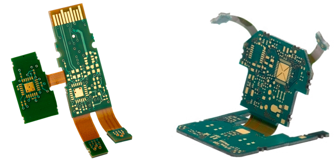
Flexible PCB connectors is another option. This eliminates any need for soldering and allows flexibility to place the different circuit boards in different locations if that is what the design calls for.
The major advantages of using flexible PCBs is they can be flexed to the point where they can be folded around corners and edges. They are also lightweight and durable, which means they can be flexed hundreds of thousands of times without breaking — ideal for moving parts and assemblies.
Some of the other benefits include:
- Vibration absorbent – due to the flexibility of the connector, it can naturally absorb shock and vibrations, which reduces the impact of the vibration to itself as well as on any solder joints and connections.
- Use in harsh environments – The material used to build flexible connects can be suitable for use in a lot of harsh environments such as water ingress, high temperatures, oil, and a lot of corrosive chemicals.
- Lower inventory or BoM cost – a single connector can take the place of multiple components, thus saving on BoM costs as well as warehouse and logistics costs.
Below is an example of PCBs connected with flexible connectors.
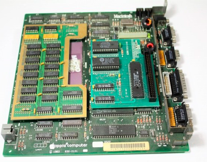
In some cases, it may be possible to design the PCBs so that there is a main motherboard with secondary or daughter board (plugged directly in to the motherboard).
Have a look inside your computer: this is the design used there. It saves on space as well as connecting cables, making the electronics compact and located all in one place. You can see an example below.
2. Standardization and Design for Assembly
Design for assembly techniques such as standardizing connectors, cables, switches, controls and other off-the-shelf items allows for less inventory and a better price due to increased order quantities per item.
It is also advisable to stay away from the very-low-cost items, as these can be unreliable, which only results in additional cost on warranties and replacement service parts later on.
Best practice when it comes to standardization is to follow guidelines within a process called design for manufacture (DFM). These guidelines include the following:
- Reduce the number of components to minimize the opportunity of defects and to reduce total cost;
- Error proof the assembly design so no errors can be made during the assembly process;
- Avoid tight tolerances where possible and design in the middle of the parts tolerance range;
- Design ‘robustness’ into the product to compensate for uncertainties in the product’s manufacturing, test and use;
- Design for part orientation and handling to minimize unnecessary and excessive movements through manufacture and assembly;
- Design for ease of assembly with minimal fasteners and ‘bottom up, one direction’ assembly;
- Utilize common parts and materials to reduce inventory and cost as well as improving assembly operations;
- Design for ease of serviceability.
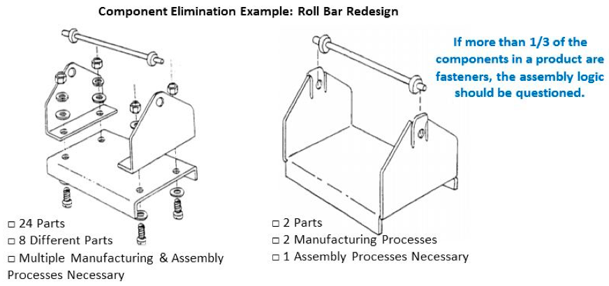
An example of this is shown in the image below. In the original design there were 24 parts in total and 8 different unique parts. It required multiple process steps to assemble the product.
The design on the right has been redesigned with DFM in mind. It resulted in a product that has just 2 parts and has just one assembly process. The cost saving between the two is significant and has been achieved simply by following a process that focuses on standardization and combining different components into a single component.
Source: http://www.slideserve.com/lenci/introduction-to-design-for-cost-effective-assembly-and-manufacturing
—
Once all of this has been done, you are pretty close to ready from a technical point of view. The next steps are to purchase the components, do a pilot run, and go in direction of mass production.


No comments:
Post a Comment