This is the fifth article in our series about what it takes to develop an electronic product in China. Let’s look at the prototyping stage.
The imaginary example we thought of, the Drone Intruder Interception System, is a complex design. It would require many different prototype models which would require different prototyping methods.
For each element, there needs to be functional prototypes that not only work and function on their own but also as a system. This allows for individual exploration of the product design, to ensure the design is as robust as possible in every aspect.
Below are possible prototype requirements for each element of the project. These are just outlines to give you the idea of how to map out your prototypes.
Prototyping Techniques
Here are a few prototyping techniques that might make sense for this project:
- CNC machined components at very low volume
- One-off fabrication of metal components or framework
- Very low volume pcb manufacture and assembly
- Stereolithography (SLA) – uses photopolymerization, a process by which light causes chains of molecules to link, forming polymers
- Selective Laser Sintering (SLS) – a high-power laser fuses small particles of plastic, metal, ceramic, or glass powders into a mass
- Fused Deposition Modeling (FDM) – a nozzle lays down successive layers of material onto a base platform
- Selective Laser Melting (SLM) – melts and fuses metallic powders together
- Laminated Object Manufacturing (LOM) – a series of thin laminates are laid out on a build platform.
We wrote an article last year about the different methods of prototyping, in case you want to go more in depth in this topic.
Drone Intruder Detection Prototypes
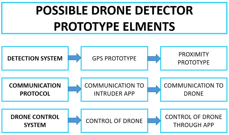
The chart below show what prototypes are potentially required for the drone detecting project. There could be some sort of GPS system which informs you the location of the intruder and could provide information such as estimated distance for your location, how long will it be before the intruder enters your property boundary, and so on.
Another system element that would need prototyping would be the communications protocol — how each of the separate parts of the system communicate with each other. What is the range the system can operate within, and what is the maximum distance your drone can operate from the control base?
These prototypes would be electronic based with minimal hardware prototyping required. However, the actual drone design itself would be mostly hardware focused.
Drone Intruder Design Prototypes
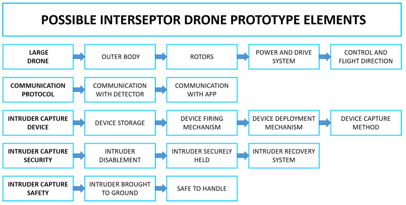
When it comes to the hardware configuration, what prototyping elements are required?
Take the large drone for example. The chart shows we would need at least the outer body as a prototype. This could be produced using the SLA or SLS prototyping method, or even a CNC machined plastic part.
Whatever method is selected, you need to understand the limitations of the mechanical strength of the prototype. It would be no good trying to determine the crash effects on the body with an SLS prototype, as the mechanical strength of the SLS material is nowhere near that of an engineering polymer which would probably be used for production. The table below shows a basic example of this.
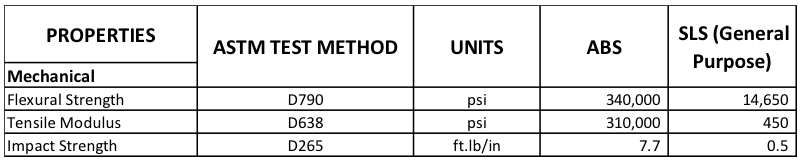
As you can see, the ABS material is far stronger than the SLS. However, the SLS prototype will be able to provide valuable information regarding the design of the product.
Drone Intruder App Prototypes
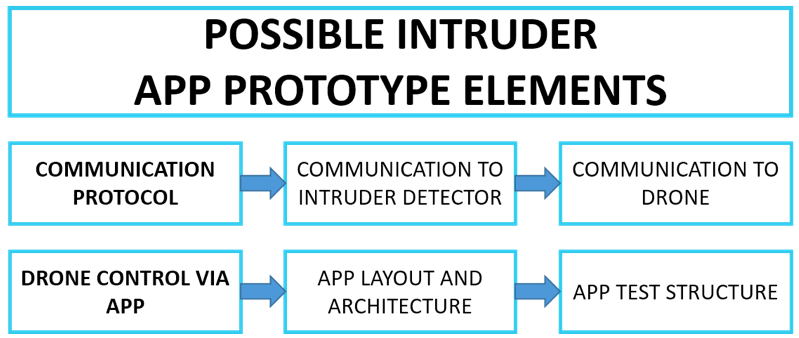
The chart below shows what app prototypes would be required. When it comes to prototyping apps, different simulation software platforms could be used for this. The key point is to test the different features of the app regarding control and communication and other key attributes.
Failure threshold testing
Once you have prototype units in place for each of the sub-systems that make up the drone project, you can start to run tests that will determine the limits of the design for each of the elements.
The two attributes for a test of the ‘firing’ mechanism would be the velocity at which the capture device was fired and the distance it travels.
If we look at the velocity attribute to start with, the prototype system would need to be set or adjusted to the lowest limits (almost to the point where the mechanism does not fire the capture device at all). The prototype would also have to fire the capture device to the upper most limits, maybe to breaking point, which would be the absolute upper failure limit for the firing mechanism.
The object of running these boundary tests is to establish the safe working limits for the design and to optimize the design around those limits.
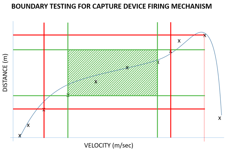
As you can see in the chart, the trend line shows a rapid drop in performance at maximum velocity. This could be attributed to mechanism failure, thus failing to fire the capture device and real distance.
The red lines indicate the limits of the design and the green lines show to ‘sweet spot’ from a setting point of view.
Inside the intersecting green lines is the optimum operating window or system tolerance to which the design team would optimize into a robust product.
I hope this was a good overview of what work would need to be done for getting to the point where a full prototype can be made. Of course it is not as linear as we made it to be. There are many feedback-and-redo loops.
In the next article we’ll look at design optimization.
No comments:
Post a Comment